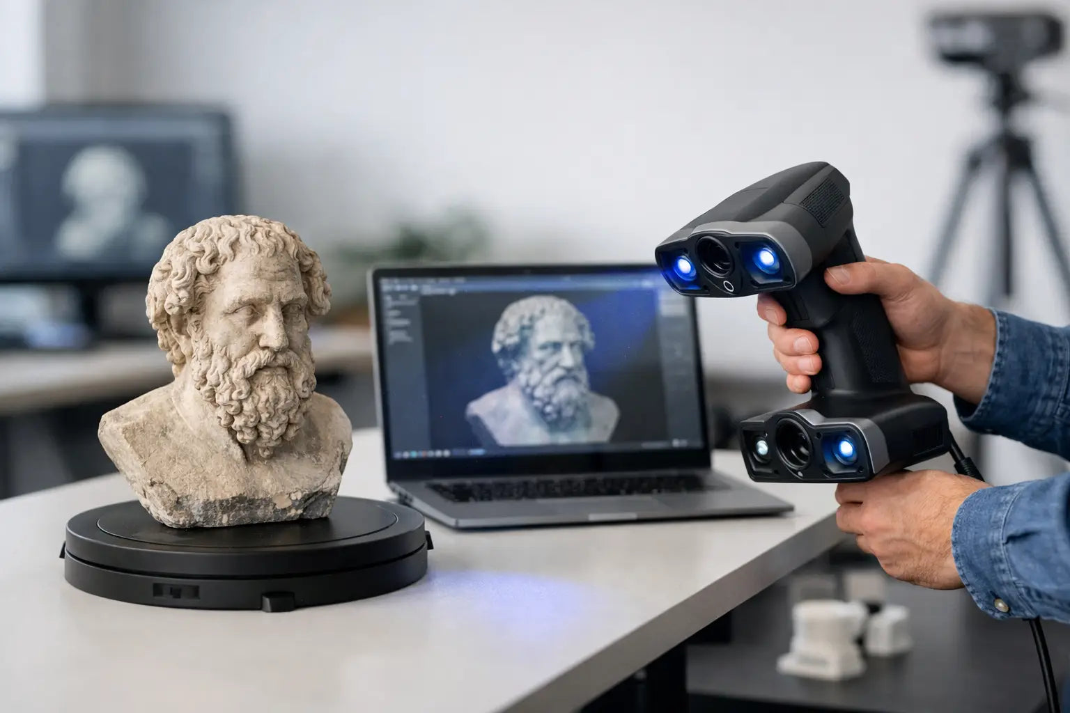
How a 3D Scanning Workflow Really Works
The first failed scan usually looks fine until you try to use it. Edges wobble, reflective surfaces disappear, and the model that seemed ready on-screen falls apart in CAD or 3D printing software. That is why a solid 3D scanning workflow matters. The hardware gets the attention, but the workflow is what turns a cool demo into a reliable result.
For makers, designers, reverse engineering teams, and serious hobbyists, the process is less about pressing one button and more about controlling each stage well enough that the next stage does not become a mess. A great scanner can still produce bad output if the object is poorly prepared, the environment is working against you, or the file is exported in the wrong format. When the workflow is dialed in, you save time, reduce rework, and get scans you can actually build from.
What a 3D scanning workflow includes
At its core, a 3D scanning workflow has five parts: planning, object prep, data capture, post-processing, and export for the final use case. That sounds straightforward, but each step has trade-offs.
If your goal is 3D printing a replica, you might prioritize complete surface coverage over tiny dimensional precision. If you are inspecting a machined part or recreating a component for reverse engineering, accuracy becomes the whole game. If you are capturing a sculpture or a person, color texture and speed may matter more than metrology-level detail. The right workflow starts by being honest about the output you need.
Start with the end use, not the scanner
A lot of scanning frustration comes from choosing settings before defining the job. Ask what the model needs to do after the scan. Will it become a mesh for visualization, a watertight model for printing, or a reference shape for CAD reconstruction? Those are different paths.
For example, a decorative object can tolerate some interpolation in hidden areas. A replacement part cannot. A face scan may need smooth texture and natural contours, while an engine bracket needs stable geometry and measurable dimensions. Once the destination is clear, scanner resolution, alignment strategy, and file format choices get easier.
This is also where budget and time enter the picture. Higher resolution captures more detail, but it also creates larger datasets, longer processing times, and more demanding cleanup. More data is not always better. Sometimes it just gives you more noise to manage.
Preparing the subject is half the job
In a high-performing 3D scanning workflow, prep is not a side step. It is often the difference between a one-pass result and an afternoon of rescans.
Shiny, transparent, black, or highly repetitive surfaces are common troublemakers. Optical scanners rely on visible surface information, so chrome tools, glass objects, and glossy plastics often confuse the system. In those cases, scan spray or temporary matting products can make a dramatic difference. They reduce glare and give the scanner a readable surface without permanently affecting the object.
Markers may also be necessary, depending on the scanner and the geometry. Feature-rich objects can self-align well. Smooth parts with few distinguishable details usually benefit from marker-based tracking. It adds setup time, but it can stabilize the capture and improve alignment accuracy.
The environment matters too. Harsh sunlight, shifting shadows, cramped spaces, and unstable turntables can all hurt consistency. Controlled lighting and a stable setup tend to produce cleaner data. If you are scanning in a workshop, clear the area and keep the object still. If the object must move, make sure the movement is intentional and trackable.
Capturing data without creating problems later
This is the stage most people think of when they picture scanning, but the smartest operators are already thinking two steps ahead. During capture, your job is not just to collect data. It is to collect useful data that aligns cleanly and supports the final model.
Move too fast and you lose tracking. Stay too long in one spot and you may create redundant data without improving quality. Miss undercuts or deep recesses and you will be patching holes later with guessed geometry. The best capture pace is controlled and deliberate.
A common rule is to work in overlapping passes. Give the software enough shared geometry between frames to maintain alignment. Circle the object from multiple heights if needed. Tilt or reposition the part to expose hidden features. If you are using a turntable, keep the rotation steady and make sure the scanner maintains a clear line of sight.
This is also where restraint pays off. If tracking drifts, stop and reset instead of trying to save a bad run. A short restart is cheaper than forcing cleanup on corrupted data. Professionals know that a confident re-scan is often faster than a heroic repair.
The post-processing stage shapes the final quality
A raw scan is rarely the final asset. Most 3D scanning workflow problems show up here, when separate captures need alignment, point clouds need cleanup, and meshes need to become usable.
First comes registration or alignment. If multiple scans were taken from different angles, they must be brought together accurately. Good overlap and proper marker use make this easier. Poor capture habits show up quickly in misaligned edges, doubled surfaces, or geometry that looks melted.
Then comes cleanup. This often includes removing floating artifacts, trimming unnecessary regions, and reducing noise. Be careful not to over-smooth. Aggressive cleanup can erase small but important features such as embossed text, sharp corners, or mating surfaces on functional parts.
Meshing follows. Here, the scan data becomes a continuous surface. Hole filling can help create watertight models, but it should be used thoughtfully. Filling a hidden base on a decorative object is one thing. Filling a missing section of a mechanical part with software-generated geometry is another. If the missing area matters, rescan it.
Texture mapping may come next for visual applications. If the scan is intended for digital display, gaming assets, cultural preservation, or product showcases, color quality can matter almost as much as geometry. For engineering tasks, texture may be irrelevant and only add file weight.
Choosing the right output for the next tool
A scan is only valuable if it works in the next stage of your process. That is where export decisions matter.
STL is common for 3D printing because it handles mesh geometry well, but it does not carry color or texture. OBJ and PLY are often better for textured models or visualization workflows. If the scan will be brought into CAD for reverse engineering, you may start with a mesh and then rebuild key geometry as parametric surfaces. That takes more time, but it produces a model you can edit, dimension, and manufacture with greater control.
This is one of the biggest misunderstandings around scanning. A scan does not automatically become a perfect CAD model. For organic shapes, the mesh may be enough. For precision mechanical work, scan-to-CAD reconstruction is often part of the real workflow. Buyers who understand that upfront make smarter equipment decisions.
Where workflows break down most often
Most scan failures are not dramatic. They show up as small mistakes that compound.
The first is using the wrong scanner for the object size and tolerance requirements. A handheld scanner that works beautifully on statues may not be ideal for small, high-precision components. The second is poor surface prep. The third is capturing incomplete geometry and expecting software to fix it later.
Another weak point is workstation performance. Large scan datasets can be demanding, especially at high resolution. If processing feels painfully slow, the bottleneck may not be the scanner. It may be the computer handling alignment and meshing. For serious users, the full workflow includes the scanner, the software, and the hardware running it.
There is also the issue of operator patience. Fast results are appealing, but rushed scans usually create slow projects. A measured workflow wins more often than a flashy one.
Building a 3D scanning workflow that fits your projects
The best setup depends on what you scan most. A product designer capturing prototypes, a maker preserving custom parts, and a small business digitizing inventory will all need slightly different workflows.
If your projects lean creative, prioritize speed, ease of use, and decent texture capture. If your work leans technical, prioritize accuracy, repeatability, and software that supports inspection or CAD handoff. If you are somewhere in the middle, flexibility matters most. That is often where enthusiast-grade gear earns its place - capable enough for serious work without becoming overbuilt for a home studio or workshop.
This is also why curated gear matters. The right scanner is not just the one with the flashiest specs. It is the one that fits your object types, your tolerance expectations, and your output goals. For creators upgrading their workspace, a smart 3D scanning workflow can sit right alongside 3D printing, modeling, and fabrication as part of a broader future-ready setup.
A good scan is satisfying. A repeatable workflow is better. Once you can move from object to usable file without guessing your way through every step, the technology stops feeling experimental and starts feeling like a real advantage.